Archive
Radwani House Museum
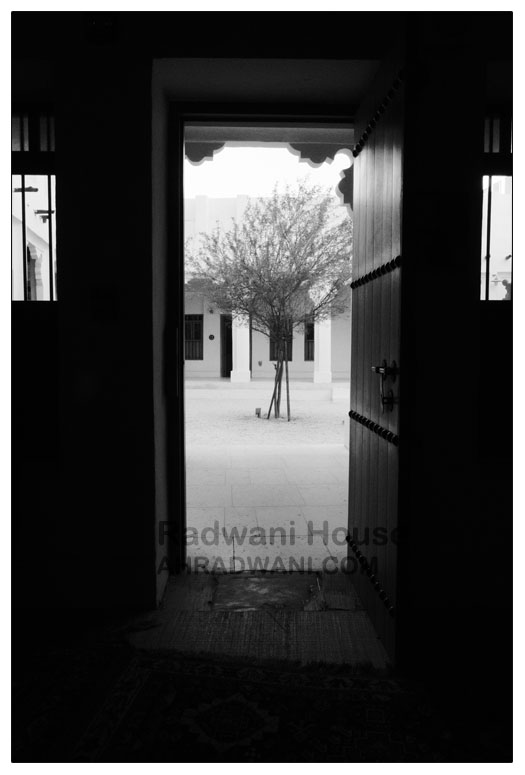
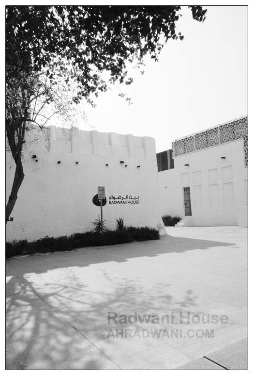
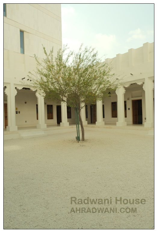
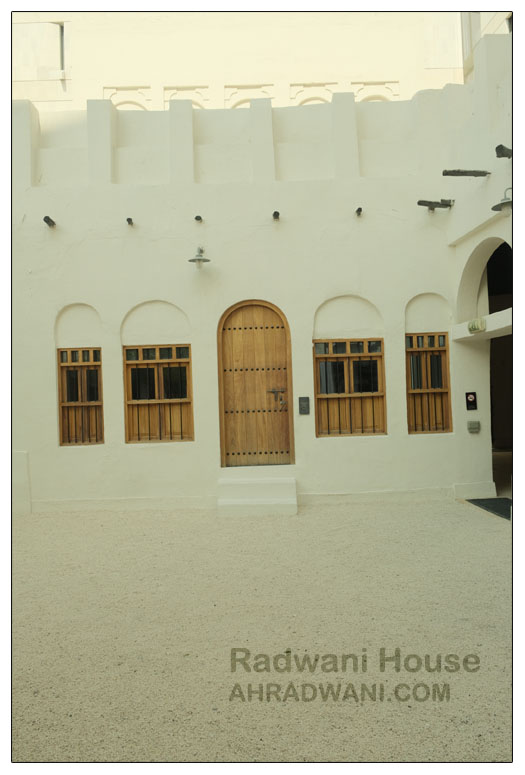
Our House located in Mshareb district been selected to be saved as a Museum to reflect Qataris Family life in early 19’s.The Radwani House been through several stages of resoration, and now it’s Open for visitors.
I create a page to post images that I take, Click Here to Jump to the Radwabi House Museum.
Here are some photos ..

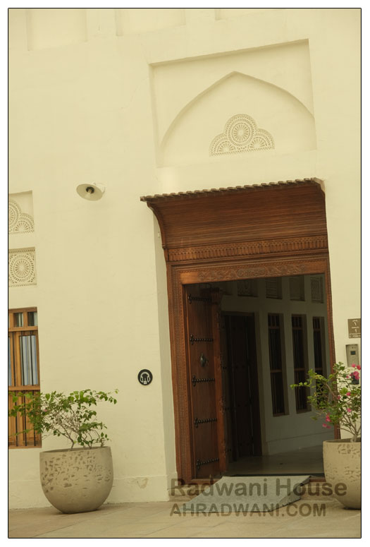
By: Ali Radwani.
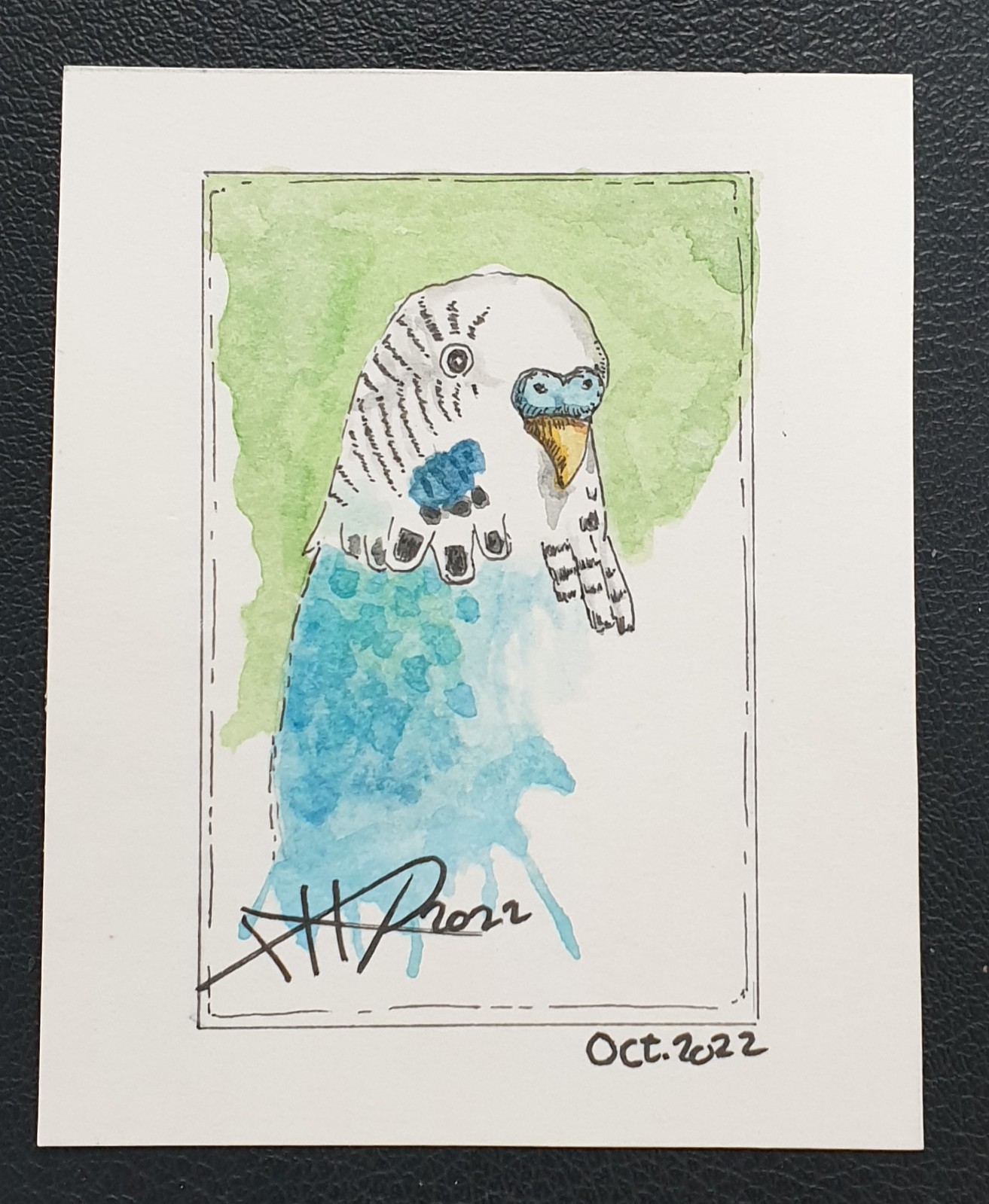
Daily Sketch: Colored Love Bird
On last September I start doing some small water_colored sketches on a 4x3in card, sketch size is almost 3x2in. Here I am posting yesterday Love-Bird sketch.
|
More of my Other Sketches Here..
..:: Have Fun with Sketching ::.. 🙂
By: Ali Radwani
Fujifilm X-T30ii Shot # 8
Subject: The BIG Five in Fujifilm X-T30ii.
This Shot: This Five logos of famouses car Brands are hangs on a wall 120 meter away. I take the photo from my car across the street using FujiFilm X-T30ii and XF 18-55mm lens.
…Click Image to Enlarge… |
| Camera in Hand, F:8, ISO:80, Shutter:1/400s, Focal-Point: 55mmLens: XF 18-55mm F2.8-4.0 OIS lens |
::.. To see all my FujiFilm X-T30ii Photos Click-Here
::.. To see all my Nikon S9900 Photos Click-Here
::.. To see all my Nikon D7100 Photos Click-Here
::.. To see all my Nikon D90 Photos Click-Here
[ For Fujifilm Simulation Recipes Click Here ]
By: Ali Radwani
Fujifilm X-T30ii Shot # 4
Subject: Photo from Qatar with Fujifilm X-T30ii.
This Shot: Driving my car, back from work, stopping on the trafic lights then using the FujiFilm X-T30ii to take this shot of a Mosque.
…Click Image to Enlarge… |
| Camera in Hand, F:10, ISO:80, Shutter:1/160s, Focal-Point:48mmLens: XF 18-55mm F2.8-4.0 OIS lens |
::.. To see all my FujiFilm X-T30ii Photos Click-Here
::.. To see all my Nikon S9900 Photos Click-Here
::.. To see all my Nikon D7100 Photos Click-Here
::.. To see all my Nikon D90 Photos Click-Here
By: Ali Radwani
Nikon S9900 Shot – 28
Subject: The Temple Face in Nikon S9900
This Shot: I take this shot in the Kids Playing section in Villaggio Mall – in Qatar- I use BW in camera and reduce the camera aperture to make it darker, it look like a photo from a museum. I am using Nikon S9900.
…Click Image to Enlarge…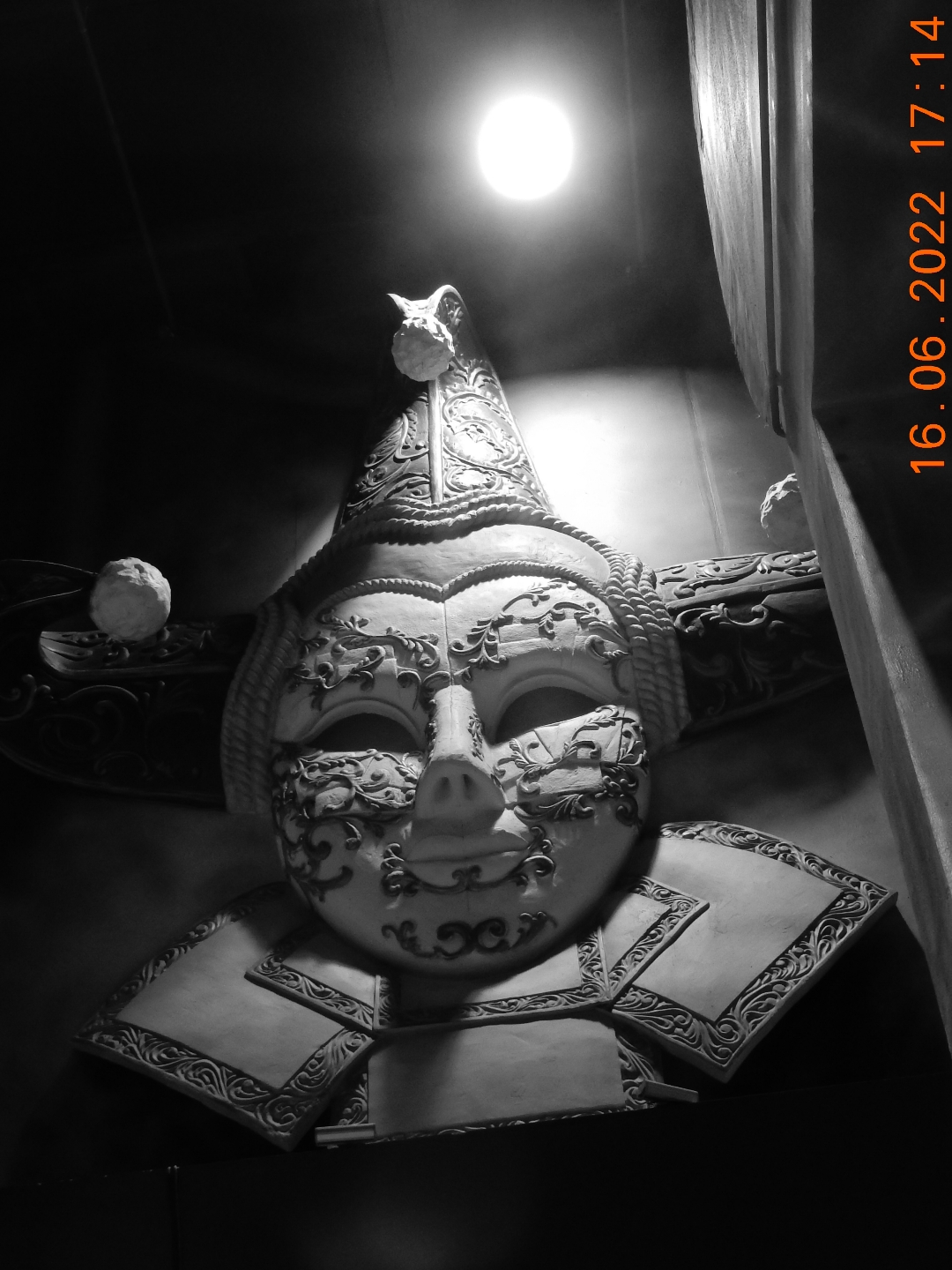 |
| Camera in Hand, F:4.2, ISO:400, Shutter:1/30s, Focal-Point:8mm |
::.. To see all my Nikon S9900 Photos Click-Here
::.. To see all my Nikon D7100 Photos Click-Here
::.. To see all my Nikon D90 Photos Click-Here
By: Ali Radwani
Nikon S9900 shot – 26
Subject: Under the Tunnel with Nikon S9900
This Shot: Some time we take the cameras beyond it’s normal capabilities, here in this shot I am using Nikon S9900 holding it by One Hand while driving the car through a shot tunnel, taking the picture from behind the car front glass that has a sun-protection shild!! After all of that I am telling my self ” why the image is not clear 🙂 ” 🙂 .. 🙂 . In general I am happy with the out-put and as sample images of Nikon S9900 I am writing the situation of taking the photos.
…Click Image to Enlarge…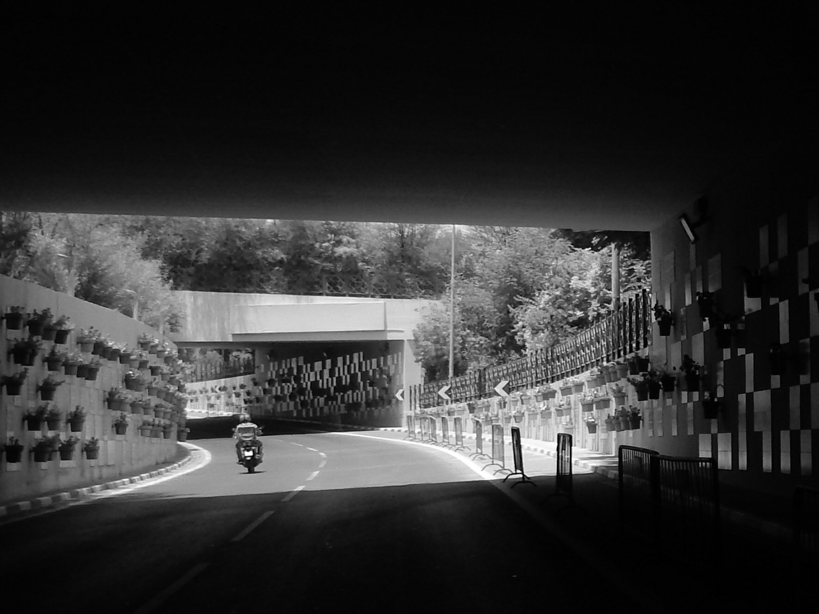 |
| Camera in Hand, F:…, ISO:…, Shutter:…, Focal-Point:…… |
::.. To see all my Nikon S9900 Photos Click-Here
::.. To see all my Nikon D7100 Photos Click-Here
::.. To see all my Nikon D90 Photos Click-Here
By: Ali Radwani
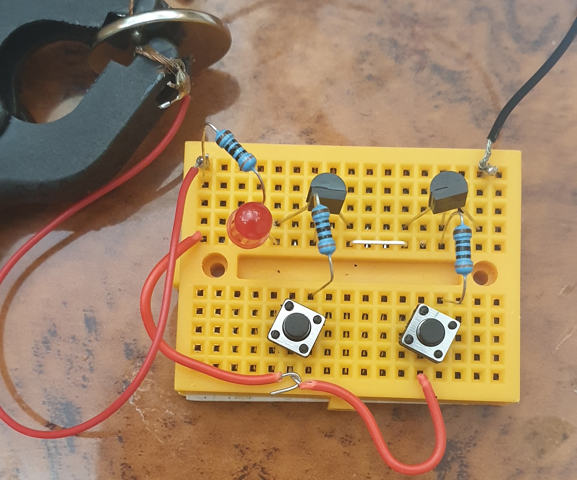
Arduino: AND-Gate Circuit
Learning : Electronic AND-Gate Circuit
Subject: To Build an AND-Gate Circuit using BC547 Transistor
[NOTE: We are working on Electronic Devices, Voltage, Resistors and other Electronic Parts that may Become HOT due to un-stable current or Wrong Wire Connections.. PLEASE BE CAUTIOUS AND TAKE SAFETY NEEDED PROCEDURES.]
In this Project we will use the BC547 Transistor to build an AND-Gate Circuit on a breadboard, so we will Not use the ADRUINO board.
What we Need
- 2 2Pin Push-Button.
- 1 LED
- 3 Resistors.
- 2 BC547 Transistor.
- 1 BreadBoard. [I am using a small 5x7cm]
- Some Jumper Wires.
- 3V Battery
Connections
- Connect Both BC547 to the BreadBoard.
- Connect Emitter of the First (left) One to the Collector of the second One (Right one). [Use Jumper Wire]
- Connect TWO Push-Buttons to the BreadBoard.
- Connect between each BasePin of the BC547 and Pin1 of each Push-Button using a Resistor1&2 [Pin1 of PushButton1 to Pin1 of Resistor1, Pin2 on the Resistor1 to BasePin of BC547.]
- Connect Pin2 of Push-Button1 to the Pin2 of the Push-Button2.
- Connect the Push-Button2 Pin2 to a Resistor3 Pin1
- Connect the Resistor3 Pin2 to the LED(+)Pin.
- Connect the LED(-)Pin to the First BC547 CollectorPin
- Connect the Battery (+) to the Resistor3 pin2, and Connect the Battery (-) to the Emitter Pin of Second BC547.
 |
 |
Run-Time
The Logic of the AND-Gate is if the BOTH Button are Pressed in same time the circuit will close and the LED turn On.
Here is a GIF clip of Running Time. |
:: ARDUINO PROJECTS LIST ::
[ Click Here to See all ARDUINO Projects ]
By: Ali Radwani
LED Fade-Off from Prototype to Gadget
Learning about : Circutes, Capasitor, Push-Button
Subject: LED Fade-off apply it on a PCB Board.
[NOTE: We are working on Electronic Devices, Voltage, Resistors and other Electronic Parts that may Become HOT due to un-stable current or Wrong Wire Connections.. PLEASE BE CAUTIOUS AND TAKE SAFETY NEEDED PROCEDURES.]
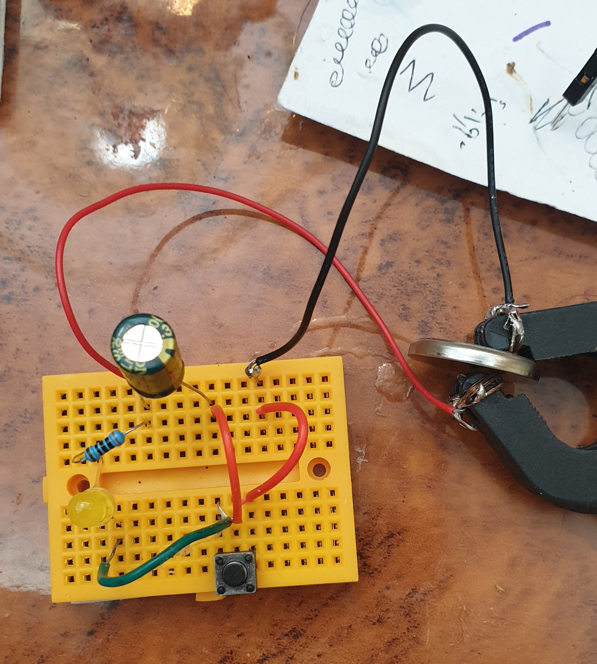
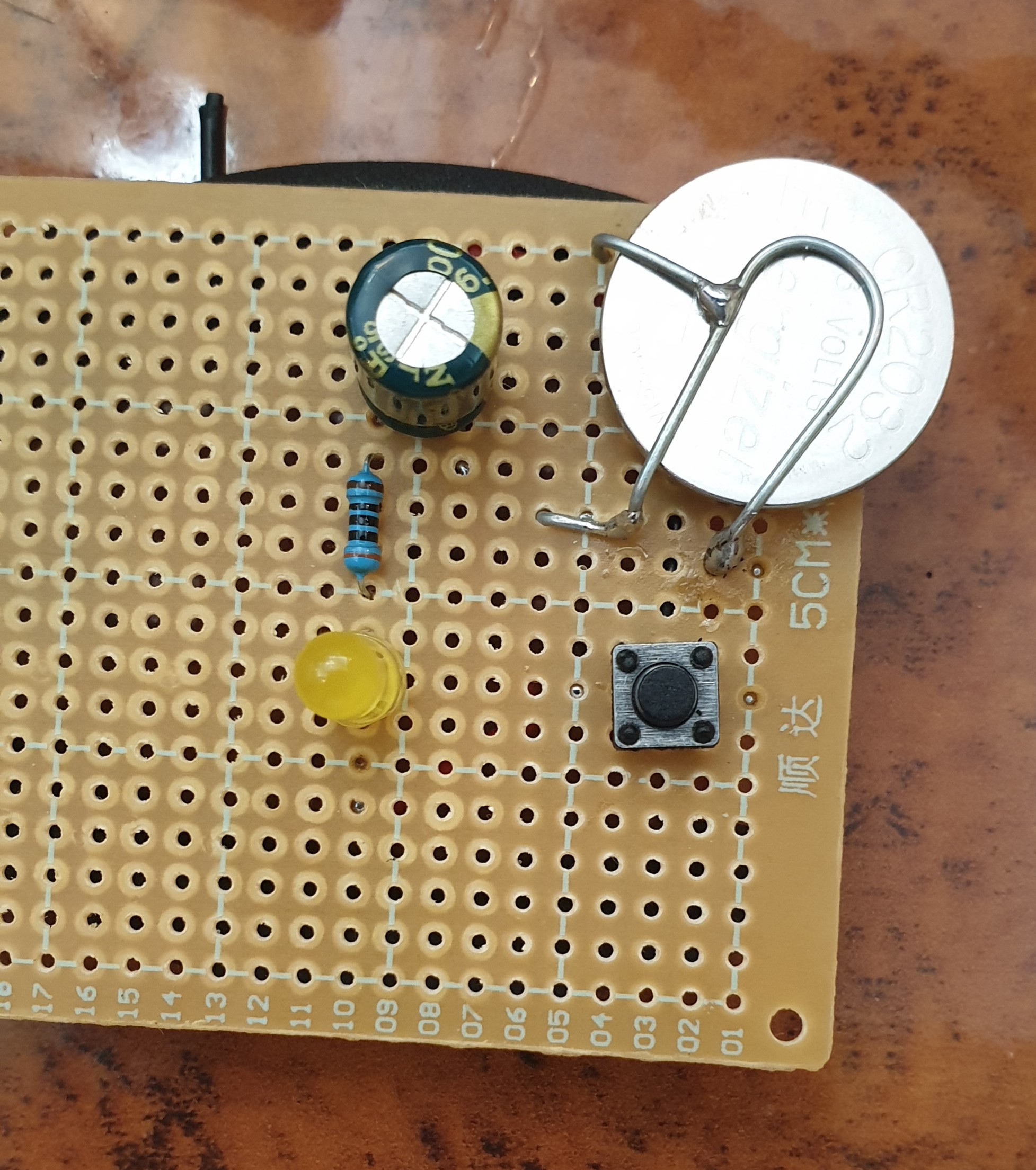
In one of my previous Post [Read Here] I did some connection on a breadboard using BC547 and a Capacitor to make an LED Fade-off in 60sec after pushing a button. In this post we will convert that circuit a simpler circuit doing the same thing from a breadboard to a PCB to be as a Gadget.
What we Need: Here is a list of what we will use:
- 1 LED (I will use a yellow one)
- 1 PCB Board 5x7cm.
- 1 1000uF 6.3v Capacitor.
- 1 Resistor 300 ohm.
- 1 2pin Push Button.
- 1 CR2032 Lithium Cell 3V Battery.
Connection: All the connections will be on a 5x7cm PCB Board, I use a thin steel wire to create a strap to hold the Battery, and:
- Connect the Negative (-) Battery to Pin1 of the Push Button.
- Pin2 of the Push Button will be connected to the Negative (-) pin of the Capacitor.
- Connect the 300ohm Resistor Between (+) Pin of the Capacitor and the (+) Pin of the LED.
- The Negative(-) Pin of the LED will be connected to the Pin2 of the Push Button.
Here is all connections on a small breadboard.
 |
Here I copy the circuit on a small 5x7cm PCB.
 |
Back side Connections.
 |
Finslly, I cut the PCB to a smaller size and Label it.
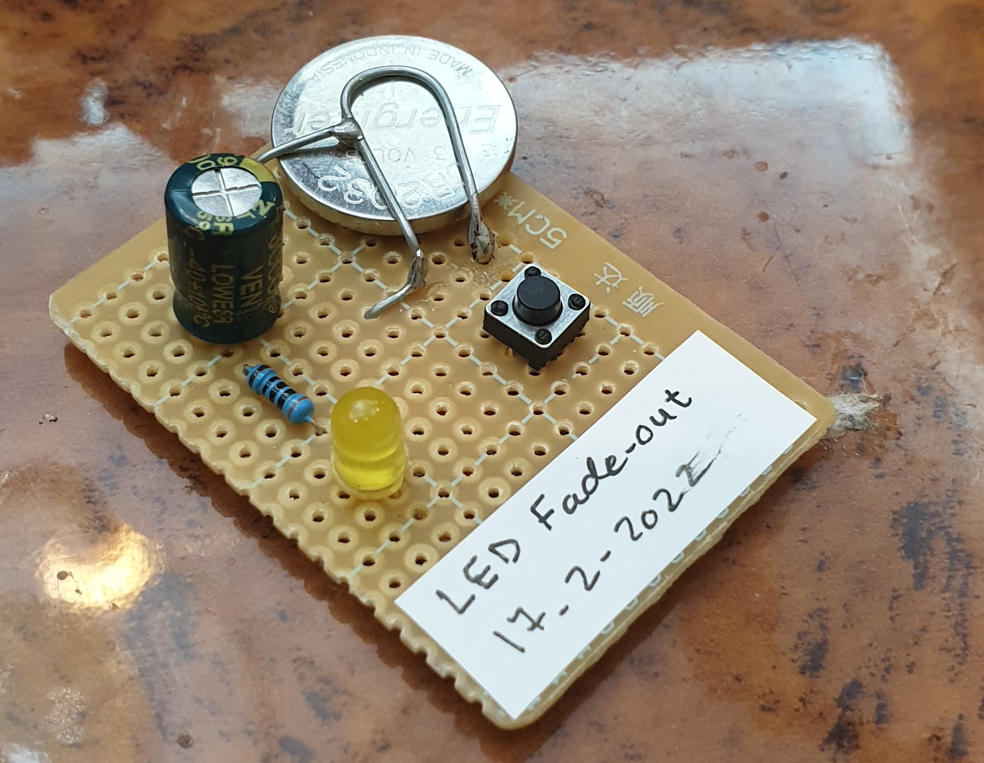 |
Now once we Push the Button the LED Turns On and Start Fading-Out. [you may need to give 5-10sec to charge the Capacitor before seeing the Fading Effect]
:: ARDUINO PROJECTS LIST ::
[ Click Here to See all ARDUINO Projects ]
To Download the ARDUINO Project [Code and Diagram] files {No Code in this Project}
By: Ali Radwani
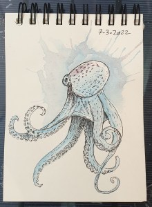
Daily Sketch Challenge: Octopus
Away from coding and reading here I am finding myself sketching some lines and dots to be an Octopus.
I am using a new pocket size sketch book, but it seems that the paper is not good for water-colos, it is quite challenge to mix colors. But at the end I will use every page of it. 🙂
Here is the sketch..
Python Project: Properties Maintenance System P12
Subject: Writing a Full Application for Properties Maintenance System [Delete Maintenance Request]
Learning : Python, Math, SQL, Logeic
[NOTE: To keep the code as simple as we can, We WILL NOT ADD any user input Varevecations. Assuming that our user will Enter the right inputs.]
In this part we will continue write the Functions in Maintenance Request Service. Here we will write the Function to Delete a Maintenance Request.
This is very easy and short Function, first we will list all the requests by calling the def show_maintenance_request, after that we will ask the user to Select the ID of the request to be Delete.
Validation
We will use simple validation code on the User input for the following aspects:
- If the user input E to Exit.
- If the user input digits or Not.
- If the ID is available in the system/Database.
- If the user input Y to confirm the Deleting prosses.
So if the user input pass all the Validations, and he confirm the Deleting, the Record will be Deleting using the following SQL Command:
c.execute (“delete from maint_request_t where m_r_id ={}”.format(int(delete_this)))
db_conn.commit()

|
We done with this part, Next we will write a code to change a request status.
:: PMS Parts ::
| Part 1 | Part 2 | Part 3 | Part 4 | Part 5 | Part 6 | Part 7 |
| Part 8 | Part 9 | Part 10 | Part 11 | Part 12 | Part 13 | Part 14 |
..:: Have Fun with Coding ::.. 🙂
To Download my Python code (.py) files Click-Here
By: Ali Radwani
Taking pictures is not my main daily practices, but when i start playing with my camera, i really enjoy my self.
Thanks for visiting my Space..


