Archive
Arduino: AND-Gate Circuit
Learning : Electronic AND-Gate Circuit
Subject: To Build an AND-Gate Circuit using BC547 Transistor
[NOTE: We are working on Electronic Devices, Voltage, Resistors and other Electronic Parts that may Become HOT due to un-stable current or Wrong Wire Connections.. PLEASE BE CAUTIOUS AND TAKE SAFETY NEEDED PROCEDURES.]
In this Project we will use the BC547 Transistor to build an AND-Gate Circuit on a breadboard, so we will Not use the ADRUINO board.
What we Need
- 2 2Pin Push-Button.
- 1 LED
- 3 Resistors.
- 2 BC547 Transistor.
- 1 BreadBoard. [I am using a small 5x7cm]
- Some Jumper Wires.
- 3V Battery
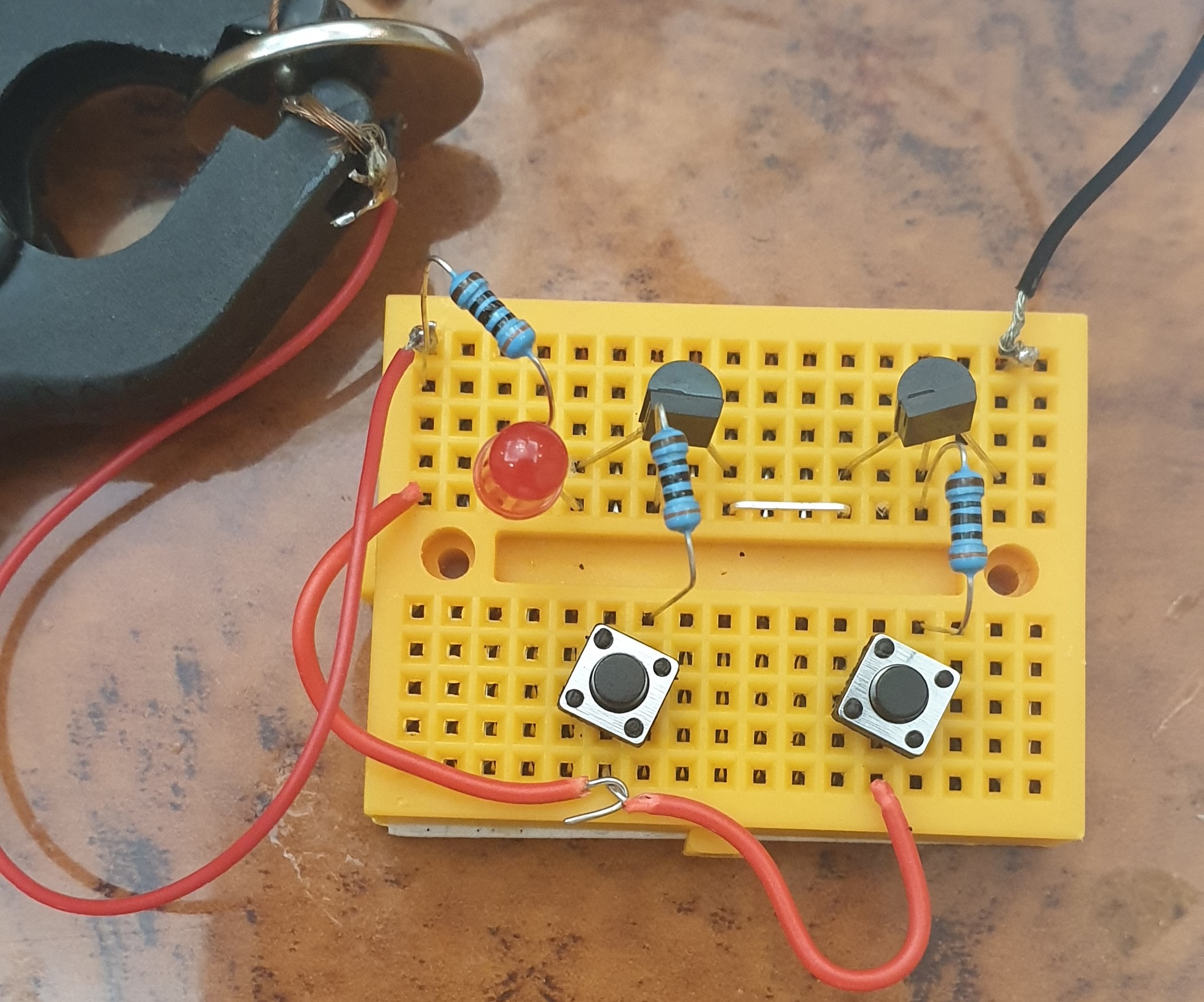
Connections
- Connect Both BC547 to the BreadBoard.
- Connect Emitter of the First (left) One to the Collector of the second One (Right one). [Use Jumper Wire]
- Connect TWO Push-Buttons to the BreadBoard.
- Connect between each BasePin of the BC547 and Pin1 of each Push-Button using a Resistor1&2 [Pin1 of PushButton1 to Pin1 of Resistor1, Pin2 on the Resistor1 to BasePin of BC547.]
- Connect Pin2 of Push-Button1 to the Pin2 of the Push-Button2.
- Connect the Push-Button2 Pin2 to a Resistor3 Pin1
- Connect the Resistor3 Pin2 to the LED(+)Pin.
- Connect the LED(-)Pin to the First BC547 CollectorPin
- Connect the Battery (+) to the Resistor3 pin2, and Connect the Battery (-) to the Emitter Pin of Second BC547.
 |
 |
Run-Time
The Logic of the AND-Gate is if the BOTH Button are Pressed in same time the circuit will close and the LED turn On.
Here is a GIF clip of Running Time. |
:: ARDUINO PROJECTS LIST ::
[ Click Here to See all ARDUINO Projects ]
 Follow me on Twitter..
By: Ali Radwani
Arduino: Morse Code Blinking
Learning : ARDUINO, Morse-Code, Electronic Circuit
Subject: LED to Blink Morse Code
[NOTE: We are working on Electronic Devices, Voltage, Resistors and other Electronic Parts that may Become HOT due to un-stable current or Wrong Wire Connections.. PLEASE BE CAUTIOUS AND TAKE SAFETY NEEDED PROCEDURES.]
Some days ago I just went through some pages of Morse-Code. Then I got an idea to write a code for the ARDUINO to blink an LED for some letters.
Morse Code: In a basic and easy way, Morse code is a Dots (.) and Dashs (-) to present alphabet characters. So A = .- ; B = -… ; C = -.-. and so on (Morse code table in Wikipedia)
Morse Code Rules:
if we assume a unit is U, then :
- 1. A Dot is 1U.
- 2. A Dash is 3U.
- 3. A Space between a part of the same letter is 1U.
- 4. A Space between letters is 3U.
- 5. A Space between words is 7U.
In our project here, the Unite U will be the Delay in Arduino, so the LED will be High for 1U to represent a Dot (.) and will be High for 3U to represent the Dash (-).
What we will Need: I will use a Breadboard, ARDUINO Nano , One Red LED, One 300 ohm Resitro, Jumper Wire.
- A BreadBoard.
- ARDUINO Nano.
- 1 Red LED.
- 1 Resistor [I will Use 300 ohm]
- Some Jumper Wire.
Connection:
- The ARDUINO Nano will be on the Breadboard
- Connect D13 on Nano to Column 11 on the Breadboard using Jumper-wire.
- Connect the Resistor on Column 11 and Column 6 on the Breadboard.
- Connect the LED Anode (+) pin on the Column 6 on the Breadboard.
- Connect the LED Cathode (-) pin to the Column 4 on the Breadboard.
- Connect the Column 4 on the Breadboard to the Cathode Row on the Breadboard using Jumper-wire.
- Connect the Column 17 on the Breadboard (Nano GND pin) to Cathode Row on Breadboard using Jumper-wire.
- Connect the Column 19 on the Breadboard (Nano 5V pin) to the Anode Row on Breadboard using Jumper-wire.
Image of the Connected Breadboard. |
The Coding: First we need to define the Dots and Dashs for each Alphbets, in this example I will do only three carecters for my Name A L I, I will create an array of 0 and 1, 0 is a dot, 1 is a dash, here is the code:
int A [ ] = {0,1} ; // 0 = dot (1U), 1 = dash (3U)
int L [ ] = {0,1,0,0} ;
int I [ ] = {0,0} ;
Here is declearing the Unite, u as Delay time:
int u = 170 ; // 1U = 170 delay.
and here is the Arduino pin I will use:
int ledpin = 13 ;
in the void setup, we will only write one line to set the pinMode(ledpin, OUTPUT)
then I create a function to read the letter array-content
 // CODE: Function to read the letters contents.

void letter(int c [], byte s)
{
      if (c[s] == 0)   // dot
        {morse1(ledpin, 1) ;}
      if (c[s] == 1)   // dash
        {morse1(ledpin, 3) ;}
}
In this code, I will let the LED to Blink in Morse code saying “ALI” [My Name 🙂 ]. You may add the Morse code in the Application and making the LED to send you message. Code Available in Download Page.
RUN TIME.. |
:: ARDUINO PROJECTS LIST ::
[ Click Here to See all ARDUINO Projects ]
To Download the ARDUINO Project [Code and Diagram] files Click-Here
By: Ali Radwani
Taking pictures is not my main daily practices, but when i start playing with my camera, i really enjoy my self.
Thanks for visiting my Space..


