Archive
Radwani House Museum post 10

This tool used to be perfume container, usually the perfume was only “rose water”, until now rose-water is poured or sprinkled on celebrants in traditional weddings.
Photo taken by Sony RX100vii camera in Black and white picture profile.
Follow me on Instagram Here
Radwani House Museum post 9

Another visit to Radwani House Museum, I take several photos in black and white also in Classic Chrome, I will post them in coming days.
Photos from Qatar _145

Driving to somewhere when this long riged trak trying to cross the road, and there is a man guiding the driver. I take some shots and wait until he pass-away.
ISO 200, F6.3, 24mm Focal-Point, shutter 1/1000s
Flowers Photography _6

Flowers in Black and white, photo taken in London 2023 with Nikon S9900 camera set to bNw .
London 2023, Post 32

Title: Green Park | Buckingham Palace
Photo taken by fujifilm X-T30ii camera in London 2023 .
By: Ali Radwani
London 2023, Post 29
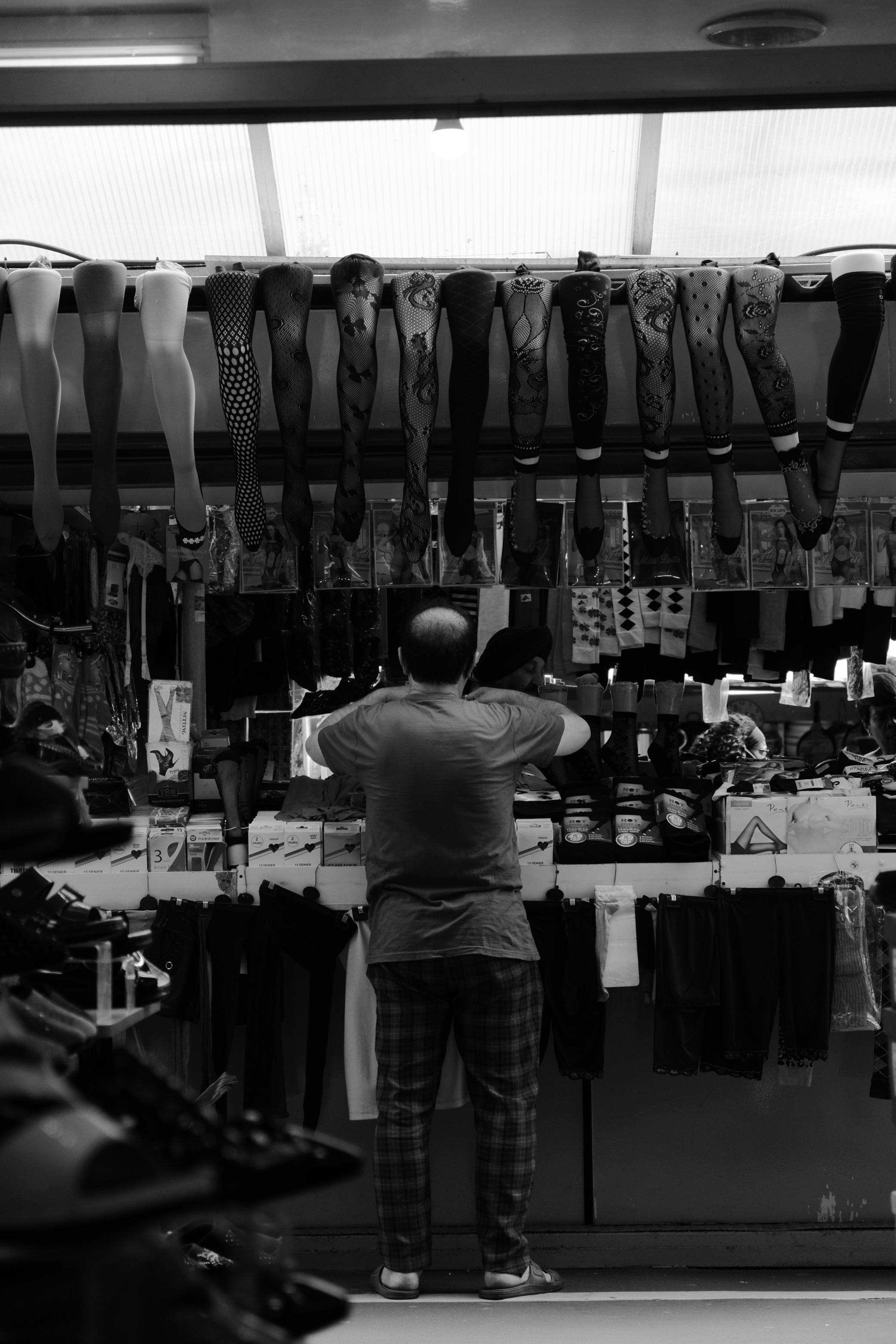
Title: A day in Shepherd’s Bush Market
Another photo of from Shepherd Bush Market, camera on and in hand set to use the ilford simulation to give a black and white images.
Camera setting:Fujifilm XT30ii F 3.6, 18mm Focal-point, ISO 800 and Shutter 1/800s.
Ali Radwani,
Sony Picture Profile – Portra400 mimic
After taking some amazing colored images from my London2023 Trip using Kodak portra 400 film simulation on my FujiFilm X-T30ii camera, I decide to keep this simulation on my camera.
Now I want to move the same look on my Sony RX100vii camera, although the attributes name are different 🤔, I try my best to reach nearest possible look.
Here are two photos using kodakportra400 looks. I save it to PP1 Picture Profile setting. And i am changing the numbers to reach best look i want.

Kodakportra400: This bike was around 3 metres away behind the fence in my back yard, and I was sitting on a chair, camera in hand with 51mm Focal-Point and F 4.5 Shutter speed 1/60s and ISO 800.

In this shot I was in the car waiting for traffic lights, I take the photo and I think its look very nice and close to what I want.
To see and copy my picture profile setting Click Here.
By:Ali Radwani
Photos from Qatar _6
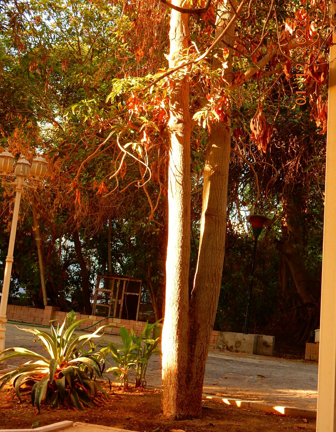
Title: Using Orange Filters
Taking a photo using Orange Filters in the Nikon S9900 camera, I take the photo of a tree during a sun-set sunny day that gives more strong color , camera in hand ISO set to 400.
By: Ali Radwani,
Photos from Qatar _8

Title: Food Delivery
Driving my car at 2pm, this Food Delivery motorbike man was checking out his distension on the mobile then start wearing the helmet. I take the shot using Nikon S9900 camera from my car on the other side of the road.
Camera setup: Black and white Photo mode, Focal-Point 5mm, F4, ISO 125 and Shutter speed 1/100s.
By: Ali Radwani
Photos from Qatar _2
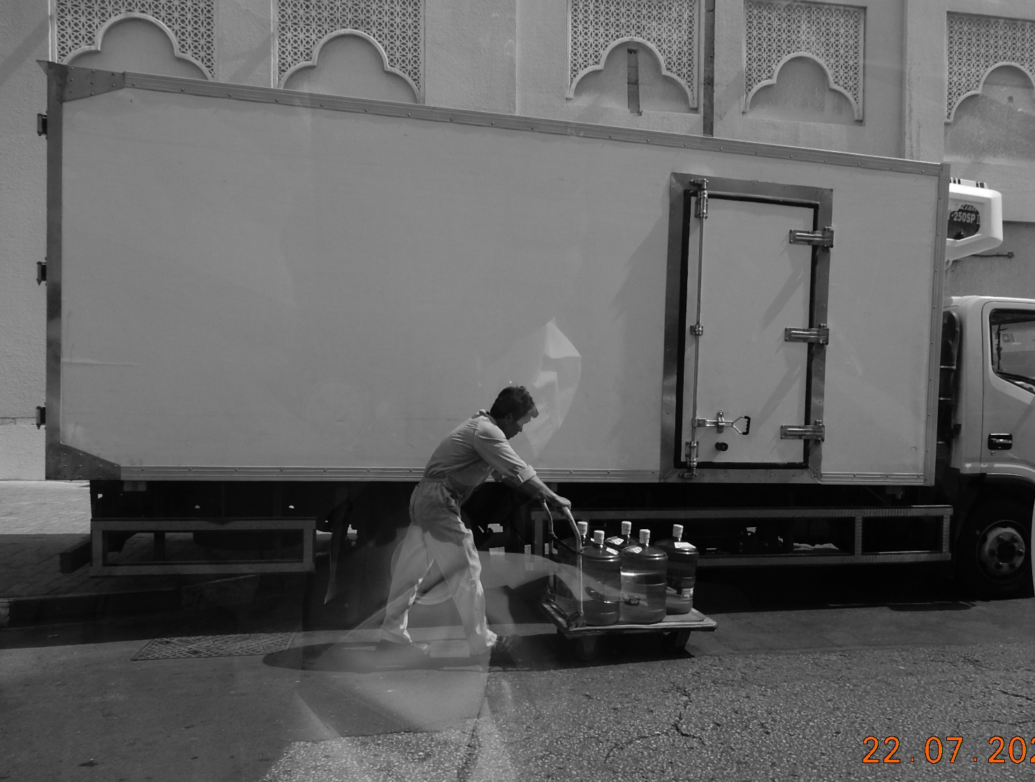
Title: Works Hard
I was parking my car and waiting for a pick-up pack, and were playing on camera setting suddenly I noticed this worker pushing the water cart, I then just raise push the Shutter with out thinking in the composition. This what I’ve got.
Camera in hand, photo form behind car glass with Nikon S9900 set’s to take Black and White photos.
By: Ali Radwani
Taking pictures is not my main daily practices, but when i start playing with my camera, i really enjoy my self.
Thanks for visiting my Space..


